To calculate a joint, follow the steps on the calcbond page from top to bottom. For every input you need to provide, detailed information is found at the very top of the calculation page. Multiple tabs offer information in an organized fashion.
¶ Step 1: Configuration Selection
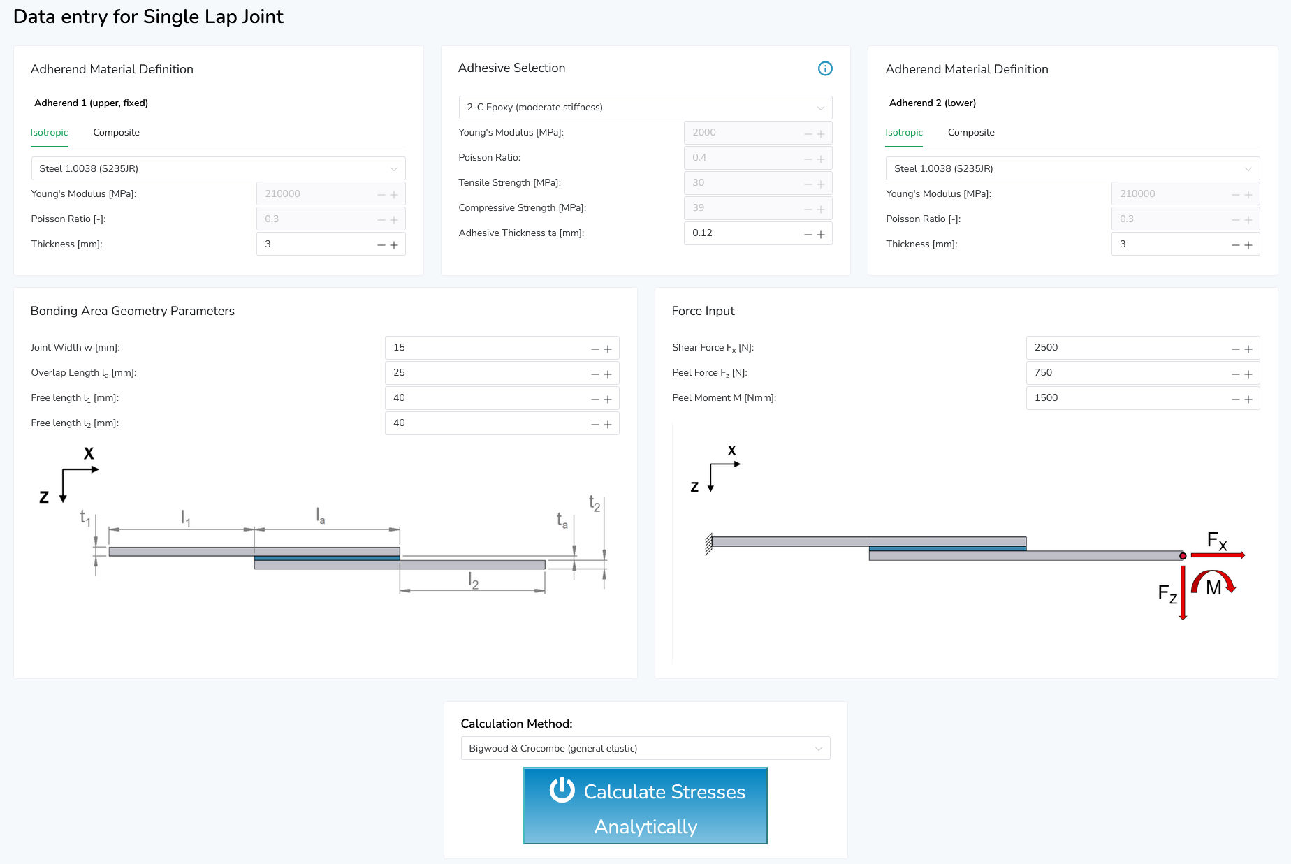
In the analytical toolbox, you can calculate the adhesive layer stresses for single-lap joints with a planar, rectangular bond surface. For your convenience, three predefined joint configurations are given for you to choose.

Click inside of one of the three boxes to select the respective configuration. Next, the user input will open up underneath.
¶ Step 2: Data Input
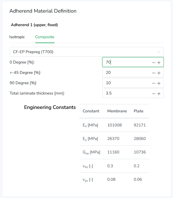
For single-lap joints, add the geometry parameters and choose an adhesive for your joint. It is possible to enter individual adhesive data, too, which lets you analyze the effect of different parameters on your joint. Next, you need to choose two adherends. For this purpose, you must select both adherends if you want to submit the isotropic or the composite data. If you are insecure about which composite material you should choose, you can use the „Material Overview“ section to compare and filter for material properties. Search, sort, and filter for multiple parameters at once. You can find the overview at the bottom of the page. For every composite adherend, you must calculate the laminate properties before moving on to the next step, by clicking on the „Calculate Properties“ button. You will notice, that after calculating the properties, the engineering constants will be displayed in the table under the button. Note that you need to calculate the properties for every composite adherend separately.

Composites Adherends in calcbond
Adherends in the analytical toolbox can be defined to be an isotropic material (e.g., steel or aluminium) or a fibre composite (orthotropic) material. To select a composite adherend material, simply switch the the "Composite" tab in the adherend material definition box. Here you will find a basic laminate generator that will calculate effective material stiffness values depending on the composite ply type and fibre orientation distribution in your adherend laminate. Refer to Material Compatibility [WIP] for further information on composite materials in adhesive bonded joints.

¶ Step 4 – Calculation Method
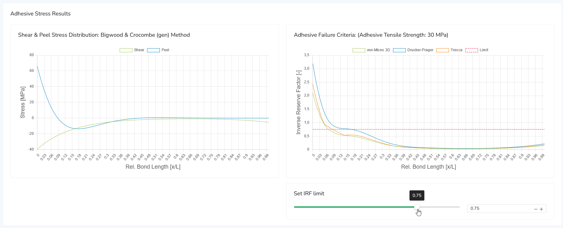
Choose a calculation method from the dropdown menu. If you need to read up on the different options, you find explanations in our wiki under „Adhesive Failure Criteria“. In case you are not sure which of the criteria is most suitable for your calculation, chose the option „Program Controlled“, which automatically chooses a suitable method for your use. To finish the process and create your results, click on the button „Calculate Stresses“ and wait for the page to reload and scroll to the results.
¶ Step 5 – Result Assessment
From here you can decide if you would like to start another calculation or save your results. When you did your calculation it got its own ID, which you can see in your new URL in your browser. This URL is individual to your calculation, so if you open it again at a later time or you send that link to a colleague, he or she can see your calculation and results in his browser. Your results will be permanently saved and retrievable.

¶ Step 6 - Report Generation
After viewing the calculation results, you can generate a nicely layed out PDF document containing your calculation data by clicking on the "Request PDF Report" button at the lower right corner.

Report generation should not take longer than 3 to 5 seconds. After the report generation is finished, you can download the document by clicking the same button again.
¶ Step 7 - Saving Your Calculation
If you want to store your calculation, you can do so in the "Save results" box on the bottom left. You can define a project name and a calculation title (or leave the default input) and then click the "Save calculation" button to confirm. The calculation is now available to view and manage in the Saved Calculations section of calcbond.

¶ Design Space Exploration
Design space exploration refers to the systematic search and analysis of different design alternatives and configurations within a given engineering problem. This methodology is often used in engineering to optimize the performance, cost, and other desired criteria of a system.
By mapping out what effect various parameter changes have on their system, engineers aim to identify the most favorable solutions, balancing trade-offs between conflicting objectives. This approach enables the evaluation of numerous design possibilities, promoting innovation and efficient decision-making.
Simulations, optimization algorithms and reduced order modeling help engineers refine their designs and enhance the overall quality of engineering solutions.
In the analytical toolbox, simple design studies can be quickly performed in the "Explore design space" section.

At present, parameters can be inspected one at a time, e.g. the thickness of one of the substrates or the adhesive material, and set which settings this parameter may take. For continuous variables, a range of values is set, and for discrete parameters, several different options can be chosen.
The following parameters are available for design space exploration:
- Adhesive material selection (discrete)
- Adherend (substrate) materials (discrete)
- Adhesive/adherend thicknesses (continuous)
- Joint length (continuous)
- Joint width (continuous)
After submitting the design exploration job, the results for the various settings are immediately made visible.
Stress distribution and inverse reserve factors are visualized and can be compared between the different settings.
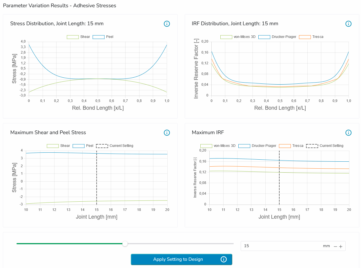
Below, a set of example plots are shown which display the results of an analysis regarding the overlapping length of a rectangular adhesive joint.
The top left plot displays the stress distribution over the bond length at the current setting of 15mm. The slider below allows the user to quickly update the plot to various settings within the range selected in the beginning.
The same applies to the top right plot, where the inverse reserve factor (IRF) distribution is shown. At any point between the ends of the adhesive joint at the currently selected parameter setting, multiple yield criteria are evaluated and visualized.
The bottom plots display the peak stresses and IRF values over all settings, making it possible to see how the parameter changes affect the overall performance of the joint and how the current setting performs.

After finding a favorable setting, it can be applied to a new calculation by pressing the "Apply Setting to Design" button, which then can serve as the starting point for another design exploration with another parameter. This enables users to quickly iterate on various parameters and find a design most suitable for the desired application.