¶ Feature Description
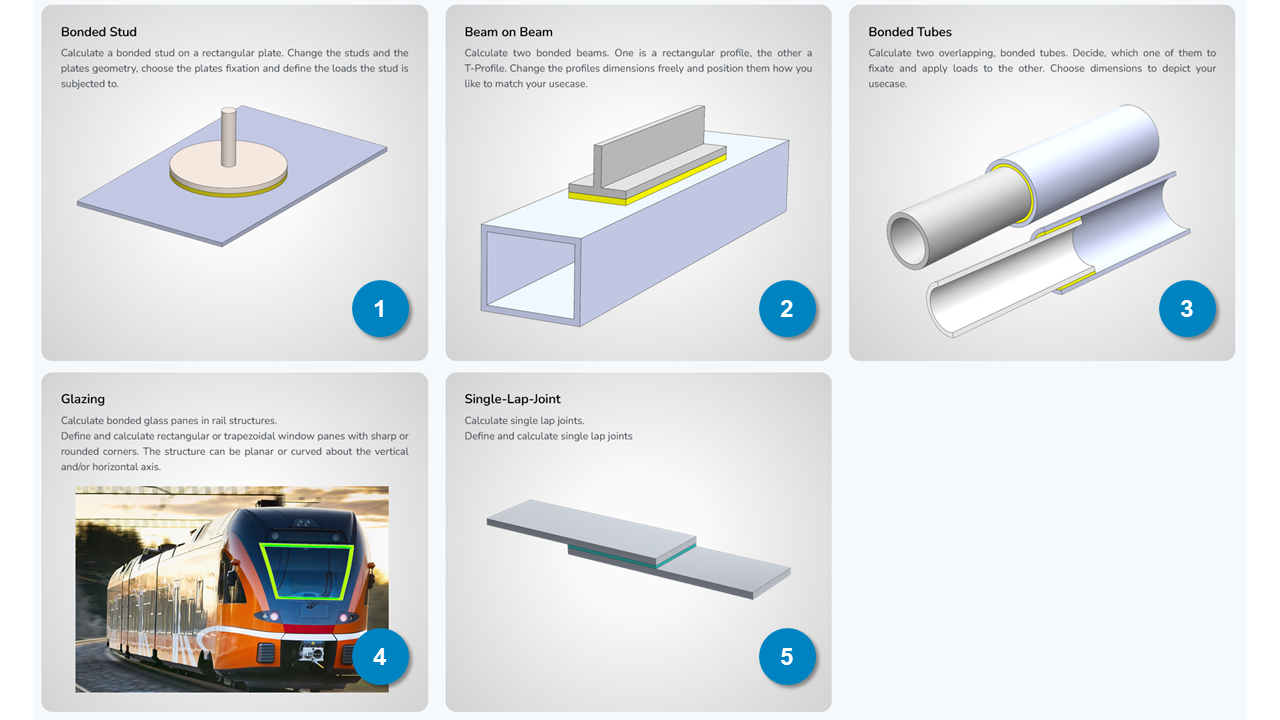
The AutoFEA module of calcbond lets you perform advanced 3D calculations of standardised bonded joints using the powerful Finite Element Method (FEM). As a Pro user, you can select pre-defined adhesive bonding use cases and set up your specific joint configuration of the selected use case using the parametric user interface. Currently, following use cases are available in the AutoFEA module:
- Bonded Stud - a stud fastener with a circular base plate, bonded onto a rectangular plate.
- Beam on Beam - an inverted T-beam bonded onto a beam with closed, rectangular cross-section.
- Bonded Tubes - two coaxially bonded tubes with a closed, circular cross-section and constant wall and adhesive thickness
- Glazing - a rectangular or trapezoidal, doubly curved window pane bonded onto a metallic frame with an offset flange (e.g. used for in rail applications)
- Single Lap Joint - the conventional joint of two plates adhesively bonded with a planar, rectangular bond surface (e.g. used for lap shear tests)
Note that, as a Pro user, you have a number of 5 calculation tokens available that automatically renew every month of your ongoing subscription. Each successfully submitted calculation request will consume 1 token. Unused tokens do not accumulate over the course of multiple months! With each new month of your subscription, your monthly included AutoFEA token number will be reset to 5.
If you would like to perform more than 5 AutoFEA calculations per month, you can acquire additional tokens in the User Portal. As long as your Pro subscription is active, these additionally acquired tokens will not expire, so you can use them at any arbitrary time during your subscription period.

¶ Workflow
To work with the AutoFEA module simply follow these main steps:
¶ Step 1: Use Case Selection
Select use case by clicking on the respective tile. The specific interface for parameter definition will open underneath.
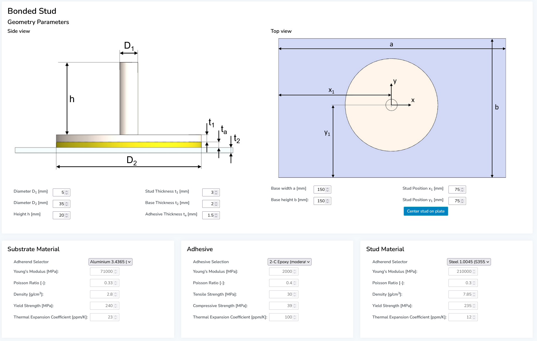
¶ Step 2: Joint Parameter Definition
Enter all design parameters and select the adherend and adhesive material. Alternatively, enter your own material data by choosing "User Defined" at the very bottom of the material dropdown menu.

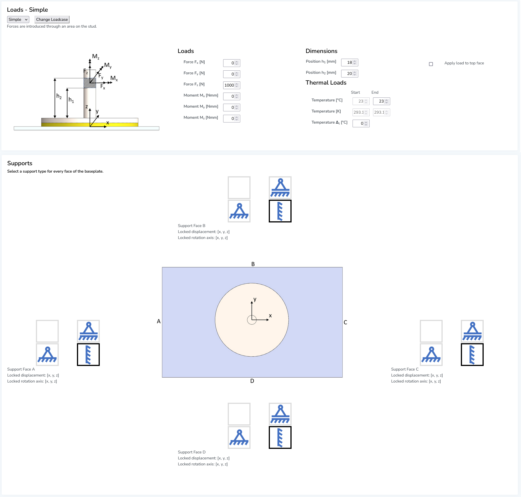
¶ Step 3: Loading & Boundary Conditions
Depending on the selected use case, different types of mechanical loads can be defined that act on the bonded joint. Also, you can define a temperature difference acting as thermal load on the entire assembly. This will induce thermal expansion in both adherends and the adhesive to account for thermally induced stresses in addition to stresses induced by the mechanical loads and component deformation.
If a manufacturer-specific adhesive (e.g., by Sika or Huntsman) is selected from the database, also the temperature-dependent mechanical properties (Young's modulus and tensile strength) are taken into account.

Apart from the loading conditions, also the specific boundary conditions (supports/fixtures) of the joint need to be defined, as they have a significant impact on the joint's structural response.
¶ Step 4: Submitting a Simulation Request
Once the joint calculation is fully defined, you are ready to submit your request to simulate it. By clicking on the "Request calculation" button at the bottom, your simulation request will be processed by our servers. You will see a progress indicator that updates with each processing step of your simulation. Once the simulation is finished and results are provided, a new section will open displaying your specific calculation results.
¶ Step 5: Result Assessment & PDF Report
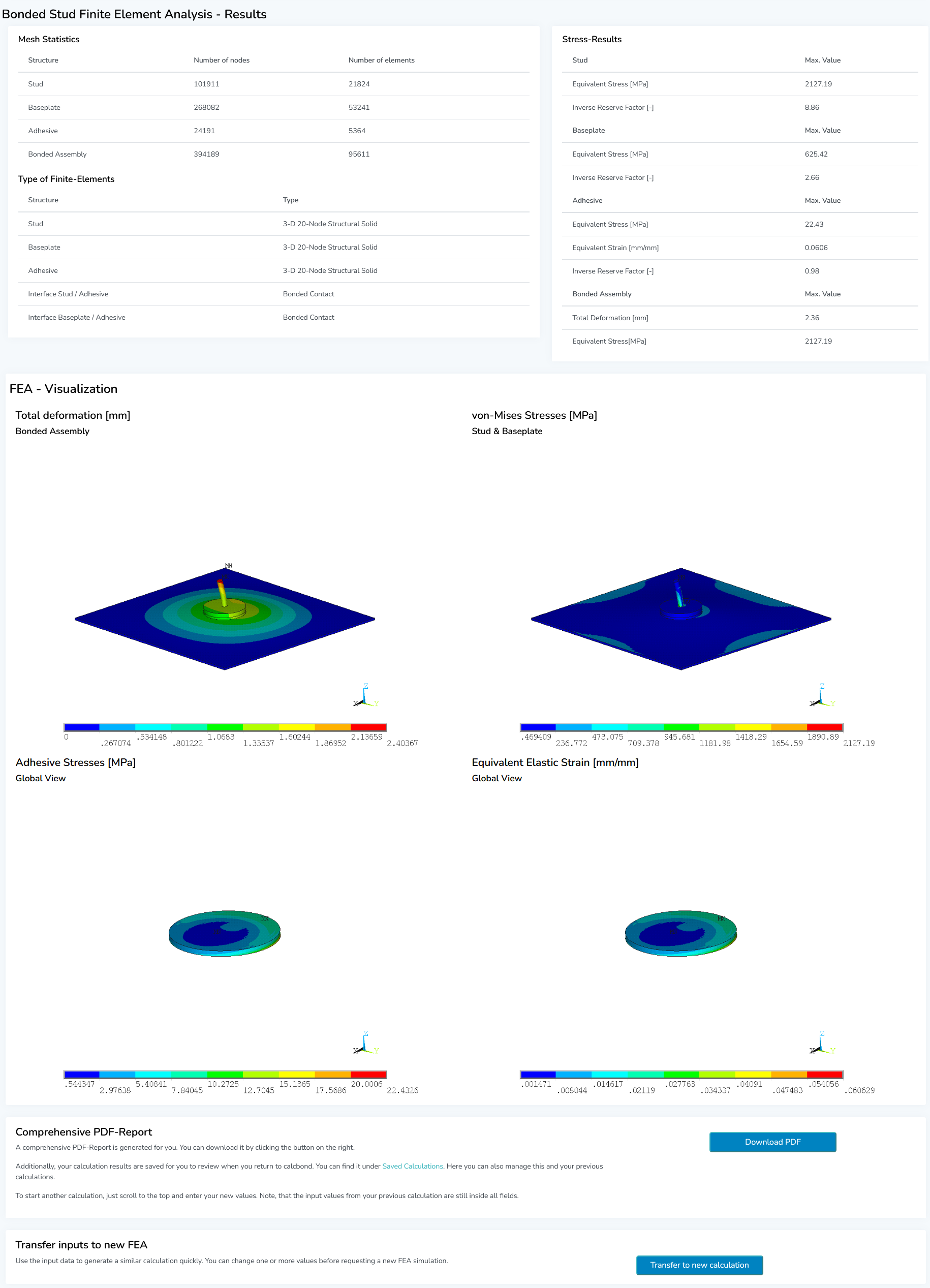
Your calculation results are shown in tabular and graphical form. The first table gives you information about the simulation model characteristics and the most important result values, such as max. occurring deformation and stresses. Following underneath are several images showing you colour-coded 3D fringe plots of the simulation results in your model.

In the last section, you will find a "Download PDF" button. Here you can view and download the automatically generated calculation report of your project as a PDF file. This report contains all relevant information such as input data, material data, calculation setup and results.
If you want to quickly set up a new calculation equal or similar to your current project, simply click on the "Transfer to new calculation" button. This will open up a new input mask with all input fields pre-filled based on the previous calculation. You can then easily modify your new calculation without having to re-enter every single parameter again.
¶ Theory Reference
In this sub chapter you will find further information about the technical background of the AutoFEA calculations.
¶ Finite Element Models
For each AutoFEA use case, the parametric joint geometries are translated into a mathematical model using the Finite Element Method (FEM). The FEM is a numerical method to solve systems of differential equations and widely used to solve complex mathematical problems that cannot be solved using analytical approaches that provide immediate and exact solutions.
In mechanical engineering, the FEM is used to generate mathematical models of structural systems (e.g., assemblies or parts) that describe their physical behaviour using a set of different mathematical correlations. These are formulated as differential equation systems and include laws to describe the behaviour and interaction of physical bodies subject to certain physical boundary conditions (e.g., external forces, accelerations, deformation or temperature). For complex real-life structures, these equation sets cannot be solved directly (for some simple structures - like a cantilever beam - exact solutions do exist that can be solved using pen and paper).
That is why numerical methods, such as the FEM, are applied to iteratively calculate close approximations of the exact solution of physical problems. In order to calculate structural components using FEM, the geometry of these components is discretized, meaning it is divided into a (large) number of finite elements with small, simplified equation sets that can each be solved quickly and easily with today's computers. That way, step by step, the physical behaviour of the entire body can be calculated. Read more about the Finite Element Method here.
Generally speaking: The finer the body is dicretized (more elements used to model the same realm), the higher the result accuracy of the calculated solution. (Disclaimer: the actual solution accuracy and result validity depends on a lot of factors which need to be considered carefully!)
¶ Finite elements used in calcbond
Finite element models can be built using 1D, 2D or 3D elements or any combination of these. In calcbond, 3D solid elements are used to model the bonded joint geometry.
¶ Solution method used in calcbond
The finite element models in calcbond are calculated using linear solution process. This means that the structural reponse of the model is calculated based on the equilibrium of the undeformed system. This approach is valid for problems with small strains/deformations and when no changes in loading, boundary conditions or any other constraints between elements are to be expected during the entire calculated event.
¶ Material laws
The physical behaviour of the adherends and adhesives modeled in the AutoFEA module is described using linear-elastic material law. This means that the correlation between strain and stress of the material follows a linear curve, meaning the increase of occuring stress is directly proportional to the applied strain.
For many engineering applications, this assumption is sufficient to simulate the mechanical response of a material up to the point of nonlinear (e.g., plastic) deformation. The linear-elastic part of a material's mechanical response is described using the Young's modulus and the Poisson ratio . For adhesive materials (or any other polymer), the tension test acc. to ISO 527-1 is often used to determine their linear-elastic properties.
In general, adhesives exhibit different types of elastic and/or plastic deformation behaviour before final failure. While highly stiff structural adhesives mostly fail in a brittle manner, semi-structural (often called "toughened") adhesives exhibit a significant amount of plastic deformation before rupture. However, in adhesive joint design, the linear-elastic limit of the adhesive's stress-strain curve is mostly used as design threshold to ensure joint safety and avoid cohesive failure. Read more about different ways to model adhesive material behaviour here.
¶ Failure criteria
In calcbond, failure of the adhesive joint is evaluated based on the stresses and strains occurring in the adhesive layer. This means that the joint failure prediction only accounts for cohesive failure of the joint. Following stress-based failure criteria are implemented in calcbond:
¶ von Mises criterion
Further content to be written...